|
|
|||
|
Note:
The modifications mentioned below have been posted |
|||
|
September through November 2006 |
|||
|
Sometime in September 2006, Gary - N1DHS suggested that he would like to replace his Mt. Lemmon 448.350 General Electric antique repeater with a little more modern one. He had a Kenwood TKR-820 repeater in service on 449.80 for several years, so it was chosen to be the candidate for the job. He presented the machine to Craig - KD7TXO and myself and we proceeded to figure out what needed to be done. You'd think we should know what we're doing, right? Right ! Read on. |
|||
|
|
|||
|
Next, it was apparent that the CAT- 300 Controller interface was not quite up to what we were planning. First priority was to suppress the transmitted PL when there was no input signal to the receiver. This would prevent the IDs, hang times and beeps from coming over the link. We had been using an ICOM-2720 for the 224.74 to 448.35 link and it had Digital Private Line capability, so we decided to control the DPL encoding of the repeater. My first crack at controlling the DPL was to install a relay in the TONE output of the repeater Signaling Unit (X57-3140-010). |
|||
|
|
|||
|
This proved the concept would work. The relay power was connected to the 12.8 VDC input power to the Signaling Unit available on CN1-1. The other side of the relay coil was connected to the COR signal on CN1-7. When COR is active, it energized and opened the path on the TONE output on CN2-1. <SCHEMATIC> One
concern was that when using this technique to cut off the DPL encoding it would remove the short PL tone burst out of the Signaling Unit after the
DPL dropped. Gary was concerned that it might cause the Digital
Controlled Squelch in his Motorola rigs to act up. Turns out it didn't make any
difference. That was a GOOD thing !! |
|||
|
It turned out that the reed relay was not so reliable. I swear that it would miss energizing sometimes. So, I moved on to a different relay. I used a Radio Shack SPST relay that was suppose to have a 100 K life cycle under full load and a 10 M life cycle under no load. Here's the installation of that one. The schematic is the same, just the names have been change to protect the innocent. |
|||
|
|
|||
|
Guess what ? This one would skip a beat once in a while too. I
was pulling out the remaining hair on my head by this time. Not only that, we discovered
that the ICOM-2720, when using the DPL Encoding/Decoding, worked just great when
going into the repeater, but when the DPL dropped on the output of the
repeater, the COR signal from the ICOM wouldn't drop until the carrier was gone from
the repeater. What a bummer !! Dave kept telling me it was the Kenwood that was causing the problem, but I was sure it was the ICOM. Turns out I was right...ha ha ! I proceeded by investigating the CAT- 300 controller and tried to figure out a couple of serious deficiencies. First, there was no way to turn off the repeater via DTMF. You could turn off the controller, but the Kenwood would revert to it's own simple repeater action. That wouldn't do at all ! Also, a method to keep the repeater cool would probably be necessary so what kind of fan could we use and how could it be controller. It wouldn't be good to leave the fan running all the time, would it? |
|||
|
January - February 2007 |
|||
|
|
|||
|
|
|||
|
March 2007 |
|||
|
|
|||
|
Monday Morning, 7 March 2007, 4:00 in the A.M. |
|||
|
I says, "That's it !! I am getting up and I'm going to go get that damned repeater audio straightened out or it ain't going up on the mountain !", says I ! I retrieved the repeater from Craig's QTH and tore it to pieces. I had noticed a LINE-OUT audio on the accessory jack that probably had proper de-emphasis. Heck, it had several stages of amplification and filtering and I figured that it must be a better method than a single feedback capacitor. I patched it in and it sounded pretty good. I installed the squelch module in and played around with it with no success. Dave - K7IOU came over and we played around with the squelch module some more using the line-out and the discriminator audio and ripped it out again. The line-out was sounding pretty good, only thing was.... IT WAS SWITCHED ON & OFF BY COR !!! DAMN !!!! YOU SHOULD HAVE HEARD THAT CHIRP ON THE SQUELCH ! |
|||
|
Tuesday, 6 March 2007 |
|||
|
Dave and I spent a couple hours Tuesday afternoon trying to figure out how to let that line-out pass through all the time, the same as discriminator audio. Dave says he can't see too good, but it was his eyes that helped me find the R45 and other components on the display panel and even remove those tiny surface mount resistors and a transistor, however, removing the components didn't seem to matter. He reinstalled the parts and had to go home. I took a ground wire and started prodding around in there and found how to turn it on continuously. VOILLA !! |
|||
|
Wednesday, 7 March |
|||
|
From there it was just a matter of time until I had the thing put back together and over at Craig's by Wednesday afternoon. |
|||
|
Thursday, 8 March |
|||
|
W8GRI - Jim told me it was still pretty sharp, I put in a 0.0047 uFD capacitor in the receiver amp in the controller. It' better. |
|||
|
Friday, 9 March |
|||
|
Gary - N1DHS says, "The Voice ID sure seems sharp !". I thought about it a while and slapped myself in the forehead and went over to Craig's and moved the capacitor to the transmitter audio output amplifier. Why didn't I think of that before? |
|||
|
Saturday, 10 March |
|||
|
Saturday morning after the breakfast, Dave and I hooked up a GM-300 donated by N1DHS to replace the delayed drop-out ICOM-2720. It works pretty darned good and the COR drops immediately. No more hang time on the 224.74 and the 146.94. There's still about a half second delay for the 448.35 to come up. We'll work on that. |
|||
|
Sunday, 11 March |
|||
|
After listening to it Saturday, I went over on Sunday and changed the capacitor to 0.002 uFD and said to myself "FINALLY ! That's the best I have ever head the audio on this repeater !" Talk about waiting until the last minute ! |
|||
|
Monday,
12 March |
|||
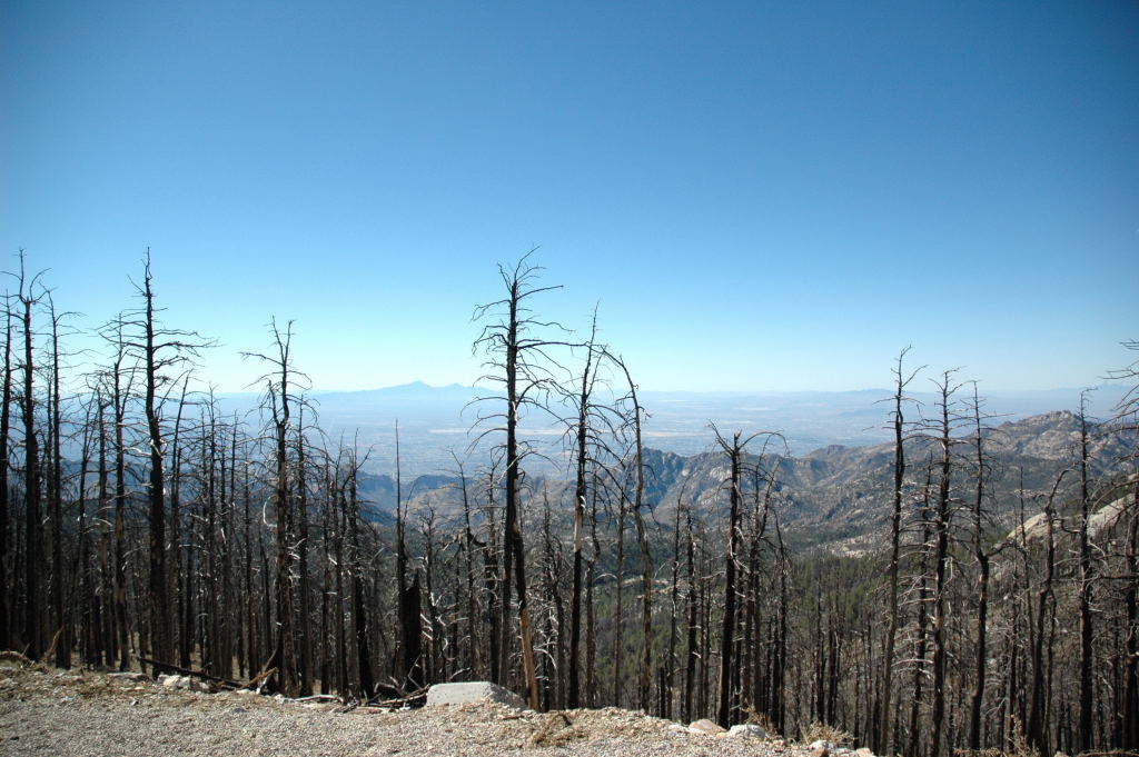
| Below are the photos taken up on Mt. Lemmon. You can see the patch of ice that defeated Gary's Tundra (sans 4-wheel drive) and the damage resulting from the big fire. Also, there are a few taken on another site on Lemmon where the Cactus guys have their shack and equipment. All in all, it was a very easy install ! | |||
|
|

|

|

|

|

|

|

|

|

|

|

|

|

|

|

|

|

|

|

|

|

|
|

|

|

|

|

|

|

|

|

|

|
|||


